Parametric Vertex Splitting for Thickness-Accommodating Quasi-Rigid-Foldable Polyhedra
failed research proposal
update: i got admitted!!
1. Project Summary
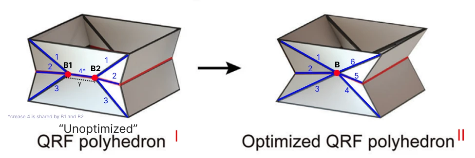
I am proposing to look at vertex splitting as a way to reduce stress concentration in quasi-rigid-foldable (QRF) polyhedra, especially when we start using thicker materials for applications such as the soles of climbing robots. Building on the work in “Origami Morphing Surfaces with Arrayed Quasi-Rigid-Foldable Polyhedrons” [1], the main question I want to answer is this:
Can we come up with a parametric approach to vertex splitting that avoids relying on a single vertex, while still keeping a high QRF rate, good shear resistance, and the zero-Poisson’s ratio property?
Over the summer, I plan to run a series of simulations that test how vertex-splitting distance and material thickness affect stress concentration at the vertex. I will reuse the exact same evaluation methods from [1] (QRF/NRF definition, fixed-boundary shear tests, and the zero-Poisson check via end-surface length change) so my results line up directly with the original designs. Since I only have Abaqus Learning Edition (which caps structural models at 1000 nodes), I will use a shell + hinge/connector model, which takes facets as shells and creases as hinge connectors. This is a standard approach in origami finite-element work (see [5] for example). By the end, I hope to show a more durable version of the QRF polyhedron that can handle different material thicknesses. That should help push these structures toward real-world use by balancing the usual trade-off between vertex stress and shear resistance, all while keeping the high QRF rate and zero-Poisson behavior.
2. Background & Motivation
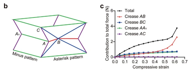
Vertex splitting is a proven technique to accommodate thick panels to work in origami while maintaining the single-degree-of-freedom kinematics of degree-4 vertices without holes. [2] In the QRF polyhedra from [1], though, the asterisk pattern relies on degree-6 vertices, which end up giving lower shear resistance than the “minus” pattern because of all the extra creases.
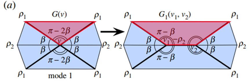
Luckily, the generalized bow-tie pattern (the same as the asterisk in [1]) has been shown to be kinematically identical to a version that uses modified two-split degree-4 vertices [3]. So the split-vertex design is expected to inherit the original folding behavior, i.e. rigid-foldable (or at least quasi-rigid-foldable) and zero-Poisson.
Nevertheless, splitting introduces more creases and trapezoid panels, which could have an adverse effect on shear resistance. At the same time, other studies on non-rigid origami have shown that even tiny changes at the vertex (such as small cut-outs or slits) can dramatically change stiffness and nonlinear behavior [5]. Together, these motivates a focused study of how the split distance affects (i) vertex stress concentration and (ii) shear performance, especially once the material gets thicker.
3. Objectives
By the end of the project, I aim to:
- Aim 1: Reproduce the baseline QRF model and all the evaluation steps from [1].
- Aim 2: Figure out how vertex-split distance interacts with material thickness and vertex concentration.
- Aim 3: See how different split distances change shear resistance.
- Aim 4: Put together a practical framework for designing thickness-accommodating QRF polyhedra using vertex splitting.
Hypothesis: Shorter vertex-split distance will preserve shear resistance but greater vertex concentration; Longer vertex-split distance will decrease shear resistance but less vertex concentration.
4. Methods & Feasibility
Due to limited time, I will be only focusing on splitting the horizontal axis of the vertex in the asterisk pattern as it intersects the 6 creases which contain the highest compressive strain [1], where thicker material will most likely contact and interfere.
4.1 Parameters
I will keep the same α and β from the original paper (they control the concavity of the side faces), and I am adding two new ones: relative thickness τ and split ratio δ.
- Relative thickness: τ = t/L, where t is panel thickness and L is the shortest crease length at the central vertex B (creases 5 or 6). I will treat the material as “thick” once τ ≳ 0.05, as Peng & Chirikjian suggested: “A pattern enters the thick-origami regime when panel thickness τ is not negligible compared to a characteristic in-plane length L (e.g., crease length or panel width).” [4]
- Split ratio: δ = γ/t, where γ is the splitting distance. For easier interpretation I will also track η = γ/L (so η = δτ).
4.2 Specimen Choice
To stay consistent with [1], I will not model a whole array. Instead I will test single-unit specimens for compression/QRF/zero-Poisson and the same fixed-boundary shear specimens they used. This is sufficient because the paper already showed that unit-level properties predict how the array behaves.
4.3 Evaluation Metrics
I will reuse the same metrics from [1] wherever possible:
- Compressive strain: ε = (h₀ – h)/h₀
- QRF/NRF rate: based on change in total length of the horizontal “red” creases
- Shear resistance: initial shear stiffness k_shear from the force–displacement curve, plus peak force before any instability
- Zero-Poisson check: normalized length of a representative end-surface edge l(ε)/l₀
For vertex durability (since we cannot resolve true peak stresses with the 1000-node limit), I will use two simple proxies from the hinge connectors following the approach used in [5]:
- Primary: total elastic strain energy summed over all creases connected to the split-vertex region
- Secondary: peak hinge moment (or rotation) in those same creases
Lower values here mean less concentration at the vertex.
4.4 Simulation Procedure
Step 1: Build and run the baseline asterisk and minus patterns to confirm I match the trends in [1] (shear stiffness ordering, end-edge invariance, etc.). Step 2: Add the split-vertex geometry (horizontal split distance γ) to the asterisk pattern. Step 3: Run parameter sweeps over τ (thin to thick) and δ (including δ = 0), keeping α and β fixed at the original design point to start. For each combination I will do both compression and shear simulations. Step 4: Plot the trade-offs, check that QRF rate stays high and zero-Poisson still holds, then propose a simple guideline for picking δ as a function of τ.
4.5 Tools
Everything will be done in Abaqus/CAE with Python scripting for setup and post-processing, plus NumPy and Matplotlib for analysis.
5. Expected Outcomes & Impact
- A clean, reproducible pipeline that matches [1] for QRF rate, shear stiffness, and zero-Poisson checks.
- Clear maps showing how τ and δ affect vertex concentration, shear stiffness, and the kinematic properties.
- A practical rule-of-thumb for choosing the split distance γ for any target thickness τ.
If it works, this should make QRF polyhedra more practical for thicker, tougher applications such as climbing-robot feet and morphing surfaces.
6. Timeline (12 weeks max)
- Weeks 1–2: Build baseline models + Python post-processing scripts.
- Week 3: Reproduce the original trends (Aim 1).
- Week 4: Implement split-vertex variants and quick smoke tests.
- Weeks 5–7: Full sweeps for compression and shear.
- Week 8: Sensitivity checks on mesh and connector settings.
- Weeks 9–10: Trade-off plots and guideline (Aim 4).
- Weeks 11–12: Write-up, figures, and package everything on GitHub.
References
- J. Li, J. Bao, C. Ho, S. Li, and J. Xu, “Origami Morphing Surfaces with Arrayed Quasi‐Rigid‐Foldable Polyhedrons,” Advanced Science, vol. 11, no. 36, Jul. 2024, doi: https://doi.org/10.1002/advs.202402128.
- K. A. Tolman, R. J. Lang, S. P. Magleby, and L. L. Howell, “Split-Vertex Technique for Thickness-Accommodation in Origami-Based Mechanisms,” ASME 2017 IDETC/CIE, Aug. 2017, doi: https://doi.org/10.1115/DETC2017-68018.
- J. Farnham, T. C. Hull, and A. Rumbolt, “Rigid folding equations of degree-6 origami vertices,” Proceedings of the Royal Society A, vol. 478, no. 2260, Apr. 2022, doi: https://doi.org/10.1098/rspa.2022.0051.
- R. Peng and G. S. Chirikjian, “Thick-panel origami structures forming seamless surfaces,” Nature Communications, vol. 16, no. 1, Apr. 2025, doi: https://doi.org/10.1038/s41467-025-59141-2.
- M. Yang, S. W. Grey, F. Scarpa, and M. Schenk, “Large impact of small vertex cuts on the mechanics of origami bellows,” Extreme Mechanics Letters, vol. 60, 2023, 101950, doi: https://doi.org/10.1016/j.eml.2022.101950.